Dominion Atlantic Railway Digital Preservation Initiative - Wiki
Use of this site is subject to our Terms & Conditions.
South Maitland Bridge Construction - Article Two
South Maitland Bridge Construction - Article Two
Subdivision Truro, Mile 40.98
In the late 1903 a preview copy of a professional paper describing the construction of the Midland Railway's bridge over the Shubenacadie River at South Maitland was published by The Canadian Society of Civil Engineers. A digitized version of the text appears below. Some formatting has been done to improve readability on this wiki.
The article included some illustrations; the scans of the drawings and photos are not the best, but are useable. Links to the drawings and photos are embedded in the article text. The text author did not use all photo numbers - there were no photos 3, 4, 5, and 6. Photo 10 was included in the published article, but was not referenced in the article text.
Another article about the construction of the piers and abutments is on this wiki at: South_Maitland_Bridge_Pier_and_Abutment_Construction.
Thanks to Laura de Boer for the reference to the article on the Archive.org website.
Please read and send in as full a discussion as possible at earliest date.
The Canadian Society of Civil Engineers.
INCORPORATED 1887.
ADVANCE P[unintelligable] subject to revision.)
N.B.—This Society, as a body, does not hold itself responsible for the statements and opinions advanced in any of its publications.
THE SHUBENACADIE RIVER BRIDGE—MIDLAND RAILWAY.
(By J. J. TAYLOR, M. Can. Soc. C.E.)
To be read before the General Section. 28 January, 1904.
PART I.
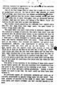
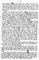
The Midland Railway of Nova Scotia (the air line between the towns of Truro and Windsor — fifty-eight miles long) crosses the Shubenacadie River on a single track bridge, known as the Shubenacadie River Bridge.
The Shubenacadie River empties into Cobequid Bay, and may be said to be really an arm of the Bay of Fundy. The point of crossing is five miles up from the mouth of the River, and near the village of South Maitland. The river at the point of crossing is about 1,220 feet wide—high water mark to high water mark.
The tide at the bridge site has a maximum range of 32.7 feet — extreme low to extreme high water. There are, of course, two tides in twenty-four hours. The tide begins to run in about two and one-half hours before the time of high tide. About five hours after the time of high tide the water has largely run out again, thus leaving the sand flats bare twice in every twenty-four hours for about five hours each time. When the tide is out only the fresh water flow is left, and the width of the river (channel) is then only about two hundred feet.
Between certain elevations of both flood and ebb tide the current is very swift, reaching a velocity of ten to fourteen miles per hour on the spring tides. There is practically no still water in the river at this point, and at the time of high water there is never more than forty minutes that boats, scows and materials can be handled on the river.
One of the many peculiarities of the tide was, that just after it had turned from flood to ebb, and when the current was running down quite swiftly along each shore, and the water lowering vertically, the current was still running up quite swiftly in the middle of the river. This continued for about one-half hour after the ebb tide set in. With the coming of the tide we had what is known as the Bay of Fundy "Bore," but not reaching a greater height than two feet. and rarely that high. (The writer has seen the " Bore " five feet high at Moncton, N.B.)
The general aspect of the Shubenacadie River at the bridge site is shown by photos 1 (photo 1) and 1a (photo 1a). These show the tide about three parts run out.
The contract for the substructure was let to the Engineering Contract Co. of New York (since gone out of business). They commenced operations May 1, 1899; suspended for the winter Dec. 1, 1899: resumed May 3; 1900; and completed Dec. 12, 1900.
Borings to determine the strata and locate the bed rock were taken in the manner described in specification, the following being an extract therefrom :—
"Note.—In regard to borings.—They were made under Mr. A. G. McFarlane's supervision, with a rig owned and operated by Messrs. McDonald & Co., of 162 Barrington St., Halifax. It was a sort of miniature pile driving arrangment with a 150 lb. dolley or hammer sliding on the drill. It was found impossible to get a pipe down about the drill through the compact gravel. etc.; and the 1¼ inch drill was turned as it went down, but drove very slowly. Once or twice the drill went down for short distances more readily, perhaps striking a streak of clay, but the gravel etc. was very compact, especially on the eastern half, growing more open as one approached the channel. In the deepest place it took two hours to drive the drill twenty feet, with four men on the lifting ropes."
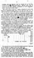
The following table shows the elevations of the rock line obtained by these borlngs and shown on the accompanying section of the river, and the actual elevations :—
| Pier No. |
Rock Line Shown on Con- tract Profile |
Rock Line Actual Built On |
Distance Below Rock Line Shown on Con- tract Profile to Actual Rock |
Remarks |
| 1 | — | — | — | Rock bare |
| 2 | — | — | — | Rock bare |
| 3 | 107.10 | 102.30 | 4.80 | |
| 4 | 101.50 | 100.00 | 1.50 | |
| 5 | 117.50 | 104.91 | 12.59 | |
| 6 | 124.20 | 122.00 | 2.20 |
One of the many lessons that this work taught was the great importance of accurately designating the strata through which it becomes necessary to go to reach the bed rock, and to accurately determine the elevation of the bed rock.
If the Contracting Co. for this work had not been overtaken by financial difficulties just before they completed the work, the probabilities are that expensive litigation would have been the result of inaccurate borings.
It will be noticed, however, that the rock line shown on the contract profile is marked “Supposed Line of Rock," and the writer might say that the contract with the Engineering Contract Co. contained a clause as follows :—
" The contract price (lump sum) hereinafter mentioned covers the works and is based upon quantities indicated on the plans annexed. Should the total work done by the contractors exceed by more than two per cent. the total quantities indicated on said plans, the excess over two per cent. shall be paid for by the Company to the Contractors at the rates hereinafter mentioned. Should it be less by more than two per cent., the shortage over two per cent. shall be allowed for by the Contractors at the same rates. The Company stipulate the right to alter the site of any of the piers and to diminish their number, provided always, the new location of any pier be in the Shubenacadie River, on the line of said Railway; in such case, if the change of the site of a pier should increase or diminish the Contractors’ work as shown by said plans and surveys, such increase shall be paid for by the Company, and such decrease shall be allowed for by the Contractors at the following rates, namely :— $15 per cubic yard of concrete in any pier, pedestal or abutment, to cover excavation, timber, iron, and all other items."
This would seem to provide a basis of payment for any extra depth the contractors might have to go with any pier, etc., to reach the bed rock, and it was made to provide for it on this work.
In the writer's opinion it is due to a contractor, and more especially when entering upon a difficult, dangerous and expensive work such as this was, to provide him with accurate data ; such as strata, through which he would have to pass in order to reach the rock; location of the rock ; facts relating to tides and currents ; and any and all information that would be of a helpful character.
In the first place it is necessary to get all this data in order to determine the proper type of structure for any given locality, and afterwards, to design it intelligently, so that, in getting it, no extra expense is incurred on the contractor‘s account.
The collecting of this data means money, and the reasons that it is not given are nearly always the disposition on the part of most companies to unduly cut down legitimate engineering expenses.
The abutments, pedestals and piers (all of concrete), occur as follows, beginning at the Windsor or western end of the bridge :—
| Back of west abutment to center of first pair of pedestals | 34'5" |
| Center first pair pedestals to center of second pair of pedestals | 32'2" |
| Center second pair pedestals to center of pier No. 1 | 31'5" |
| Center Pier No. 1 to centre Pier No. 2 | 42'0" |
| Center Pier No. 2 to centre Pier No. 3 | 219'6" |
| Center Pier No. 3 to centre Pier No. 4 | 219'6" |
| Center Pier No. 4 to centre Pier No. 5 | 219'6" |
| Center Pier No. 5 to centre Pier No. 6 | 219'6" |
| Center Pier No. 6 to back of east abutment | 222'6" |
| Total | 1240'6" |
The superstructure on the above is arranged as follows, beginning
at the Windsor or western end of the bridge : —
98 feet of steel trestle between west abutment and pier 1,
40'2" lift span, pier 1 to pier 2 (for the passage of small-craft).
215'0" each—five spans—pier 2 to east abutment.
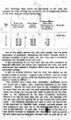
The contractors for the sub-structure decided to make the western (or Windsor) side of the river the base of their operations for the assembling and mixing of the concrete ingredients. Here they erected cement sheds, set up a stone crusher, laid down the mixing platform, installed the machinery for the operation of the cableway, and made a general working yard.
One of the first things done by them was to span the river with a Lidgerwood cableway, the line of which was parallel to centre line of bridge, and twenty-four feet distant southward therefrom ; or in the position that the bucket, when lowered, would just land on the south end of piers when they were at elevations halfway between high and low water, but, owing to the batter, would not land as the pier was built up past this elevation.
The wooden towers supporting the cableway were erected about fifty-five feet back from high water mark ; the span (tower to tower) being about 1,380 feet.
The main cable—two and a half inches in diameter—passed over the towers at a height of sixty-six feet above high water, and was anchored into the ground about ninety to one hundred feet back of each tower by being secured around three heavy hemlock logs (" dead men "), which were laid in trenches some six to eight feet deep, and heavily weighted down with stone. These towers were built of big timber, very strongly put together and guyed back. Considerable difficulty was experienced in getting this cable stretched across the river and up on the towers. It was first carried over the eastern tower and secured at that end. When all at work on the flats on the first day of trial, the " Bore " came along, and when the tide went down again and the flats were bare, eight hundred feet of the cable was buried below five feet of sand. The cable was raised and in position three days later. But, it is to be borne in mind that this does not mean three working days of ten hours each, but snatching a few hours each day when the tide was off the flats.
The utility of this cableway in the building of these piers cannot be too highly spoken of. Men and materials were transferred from any point to any other point on the cableway at all times. It was rarely out of order, and gave endless satisfaction. Indeed, it seems hardly too much to say that the work could not have been done without it.
As previously stated, all abutments, pedestals and piers are of concrete, surmounted by granite bridge seats two feet thick. The total quantity of concrete in this work is about eight thousand cubic yards, and cement averages one and one-half barrels to the yard.
The concrete is in three grades :—
| No. 1., used from the rock to two feet above low water, and of the following proportions :— | ||
|---|---|---|
| Cement | 1 | |
| Sand | 1½ | |
| Gravel | 1 | (not over ½ inch dia.) |
| Crushed stone | 3 | (not over 2 inch dia.) |
| No. 2., used for facing—one foot thick—from two feet above low water to under side of bridge seat, and of the following proportions :— | ||
|---|---|---|
| Cement | 1 | |
| Sand | 2 | |
| Gravel | 1 | (not exceeding 1 inch dia.) |
| No. 3., used for hearting, from two feet above low water to under side of bridge seat, and of the following proportions :— | ||
|---|---|---|
| Cement | 1 | |
| Sand | 1½ | |
| Gravel | 1 | (not over ½ inch dia.) |
| Crushed stone | 4 | (not over 2 inch dia.) |
All the concrete ingredients in this work are the very best of their several kinds. The mixing was done by hand, most thoroughly. Cement used was J. B. White & Brothers' English Portland. Sand, clean and coarse from Five Islands, on north side of Cobequid Bay, thirty-five miles from bridge site, and brought in schooners. Gravel from DeBert beach, on north side of Cobequid Bay, twelve miles from bridge site, towed on barges and screened to size. Stone from a vein of quartzite located in a bluff at the river side and one-quarter mile up river from bridge site, brought to assembling yard by scows, hoisted out in one yard buckets by steam derrick, and crushed alongside mixing platform. Some boulder stone was also picked up along the shores and crushed. After concrete was mixed up it was shovelled into one of three one yard buckets, picked up and sent to destination on the cable. While one loaded bucket was being sent out another was being filled.
An idea of the celerity with which the cableway worked can be had from the following note :—
The average time consumed in sending a loaded one-yard bucket of concrete from mixing platform to No. 5 pier (a distance of 790 feet), and returning empty bucket to mixing platform, was three and one quarter minutes. This was for a run of 1,580 feet, hooking and unhooking, raising and lowering the bucket.
The supply of water for concrete mixing and for boiler use was quite a problem, and the work was often handicapped owing to an insufficient and variable supply.
The writer does not propose to dwell at any length on the methods of construction used in building the west abutment, the four pedestals, pier No. 1, and the east abutment. This was dry or shore work, and comparatively simple. Concrete for the first three of these was simply wheeled from the mixing platform to place. Concrete for the last (east abutment), was sent over on the cable. The east abutment did not go to rock, but is founded well down into the hardest of hard pan overlying the rock. The pile foundation shown on section " D " was not adopted. [Editor's note - section " D " is part of the accompanying section of the river drawing.]
Pier No. 1 was oblong in shape, battered 1 to 12 on all four sides, encased with 12 x 12 bay shore spruce permanent casing from low water up to one foot below extreme high water. (All timber used throughout this work below low water is white hemlock). Foundation dimensions, 23 x 13 ; dimensions under bridge seat, 6 x 16 ; thickness of this bridge seat, 15 inches as it carries only a light span.
Each stick secured to the two below with it ¾ inch square iron drift bolts passing through 2½ timbers, one within one foot of each end of a stick and not more than six feet apart.
Abutments and pedestals were built in three-inch deal moulds, afterwards removed.
Piers 2, 3, 4, 5 and 6 were founded by pneumatic process. Heavy timber caissons being in each case carried down through the overlying strata to the bed rock below.
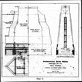
A general idea of the construction of these caissons can be had from plan " A." They were built at an old shipyard about three-quarters of a mile up river from the bridge site. They were built on launchways, christened and launched similarly to a vessel. They were oblong and with a cutwater on each end.
| Outside length point to point | 62 feet | |
| Inside length point to point | 56 feet | |
| Outside length shoulder to shoulder | 38 feet | |
| Inside length shoulder to shoulder | 35½ feet | |
| Outside width | 24 and 26 feet | |
| Inside width | 19½ feet | |
| Outside height, shoe to top of deck | 10¼ feet | (on 3 tier roof, and 1 |
| Inside height, shoe to roof of deck | 7 feet | ft. less on 2 tier roof.) |
They are built of 12 x 12 selected white hemlock, and lined inside (roof and sides) with 3-inch hemlock plank, and okum caulked ; sides and roof double 12 x 12 timbers in case of Nos. 2 and 5.
In view of the possibility of having to sink lower than indicated by the profile, the caissons for Nos. 3 and 4 were strengthened by an additional course of 12 x 12 inch timber on the roof, making three courses in all, the first two being laid transversely, and the upper course laid diagonally, and by 12 x 12 vertical timber, laid close along the sides and cutwaters (making three courses in all), and 1 inch screw-bolted through the two original courses of side timbers at top and bottom of verticals, and drift bolted in between, and also edge bolted (the one vertical to the two adjoining it), with one inch drift bolts.
Photo 2 shows the caisson "Z. J. Fowler" for No. 4 pier, strengthened as above described, and on the way down from the shipyard to the bridge site. This view shows very little of the caisson proper as that is submerged. It shows the first three 12 x 12 courses of crib timber above the caisson roof, also the first steel pneumatic section, the air admission pipe, and the blow out pipe, and the upper timbers of a very special feature of these caissons, namely the mooring crib, to which was secured the heavy steel cables which held the caisson in position against the fierce tides.
As shown by plan " A," all these caissons were braced against pressure from without by four 12 x 12 (caissons Nos. 2 and 5), and four 12 x 18 and 12 x 24 (caissons Nos. 3 and 4), hemlock timbers reaching across the caisson or working chamber, and placed just above the shoe. These timbers were cut about four inches short, and any slack taken up by hardwood keys at one end of each brace.
These transverse braces were spaced one at each pair of shoulders of caisson, and two equi-distant between. Any tendency to spread outwardly was taken care or by four 1½ inch iron rods passing through the walls to the outside of the caisson, heavy nuts and washers on outside, and adjusted by turnbuckle within. These rods were spaced similarly to timber braces ; all as shown by plan " A."
The first steel pneumatic section (eight feet long, 3 x 5, with rounded ends) for the passage of men and materials, was always built into the roof before launching. These sections were sometimes eight and sometimes twelve feet long. They were bolted through their flanges to the first or lower tier of roof timbers (and not as shown on plan " A"), the upper tiers of roof timbers butting against them, and any spaces being filled with grout.
The roof timbers of caissons were drift bolted along the edges to each other and to the upper courses of the side and cutwater timbers.
The mooring crib, of which there were two to each caisson (one fore and one aft of the shaft) was four timbers (or four feet) high above the deck, each twelve inch course screw-bolted to the two below it, and the lower two courses screw-bolted through the caisson roof. The upper course was 12 x 12 hardwood, through the centre of which the main fore and aft anchoring cables played.
The side timbers of caissons were bolted together horizontally and vertically with ¾ inch drift bolts 22 inches long, 3½ feet centres, and after the three inch lining was spiked on inside, 7/8 inch screw bolts 28 inches long (for two course side) and 40 inches long (for three course side) were put through, head, nut and washer on each bolt.
Before towing the caisson to approximate position, four or five of the 12 x 12 courses of the crib timber were built up on the roof, so that a certain quantity of concrete could be put in before finally locating the caisson.
The writer will now endeavor to describe the means and methods used in towing the caissons out to approximate position, holding them there, and finally locating them.
Large, round log, stone filled crib anchors were placed on the flats, about three to four hundred feet up and down stream of each pier centre. These crib anchors were about 12 x 12 x 12 feet ; 1¼ inch iron rods, 13 feet long, went through the four corners, two heavy logs underneath, around which was secured the 7/8 inch steel cable, which came up through the stone filling. and having an end loop through which was passed the mooring cables from the caisson. A day or two previous to the setting of each caisson, a scow was anchored quite near its destination, and the caisson ends of the six steel mooring cables (the other ends of which had been secured to the crib anchors) were brought on board the scow ready to be transferred to the caisson when she was towed to approximate position alongside. These mooring cables were arranged three up and three down stream of the caisson. The direct up and down stream cables were 1¼ inch diameter, and the four breast lines 7/8 inch diameter.
The caisson having been towed from shipyard and beached on the flats near the bridge site on one daylight tide, was towed to approximate position on the day following at high water, and the ends of the six mooring cables passed from scow to caisson and there secured. Just enough concrete to enable her to float on the tide immediately following was then put on the roof. This was done on account of the buoyancy of the large amount of timber in the caisson being so great, and the time between tides being so short that not enough concrete could be put on between two succeeding tides to hold it down.
If the weather and tide were at all favourable, and nothing unforseen occurred, it was finally located on the third daylight tide, and tended down to accurate position until it grounded, by slacking out and taking in the different cables ; twenty to thirty men being on board for that purpose.
Perhaps this imperfect description might give the impression that the locating of these caissons on the different pier sites was easy. On the contrary it was always attended with great difficulty and danger. For instance, in the case of No. 5 : being a trifle late in towing it out from the shore they missed transferring all the mooring cables from the scow. Those cables that were secured could not hold it against the strong ebb tide, and it went two miles down the river before being beached. It was brought back on the next flood tide and successfully moored in approximate position, but on the succeeding night tide it broke away from the moorings, overturning one of the heavy stone filled crib anchors, and pulling out the special mooring device on the roof (which up to this time had only been drift-bolted through the roof, but which was afterwards screw-bolted.) These damages being repaired, it was finally located eight days later.
In the case of No. 4 (the last one) this caisson was located in approximate position as described, and the first batch (or floating load) of concrete put on the roof. It rode safely over the succeeding night tide and the next day at high water was accurately located, and was being tended down as described when, by one of the many freaks of tide and current, the great force of the ebb tide bore directly on the up stream west side. Two of the breast lines parted, and it grounded several feet off position. On the following day the same process was gone through, but the strength of the tide was so great that it could not be pulled into position. The men had just been taken off by the cableway to wait until next day, when one of the lines parted and the caisson turned bottom up. Preparations were immediately made to right it, and the day following in attempting to do so, it turned a complete revolution, parted all mooring lines and went bottom up four miles up the river on the flood tide. It was brought back to the shipyard, the floating load of concrete (which all these upturnlngs and buffetings had failed to dislodge) was removed, and was righted, repaired, and finally located two weeks later. These are only two of the many similar instances which occurred during the progress of this work.
We have now the caisson located in proper position on a pier site, and ready to proceed downward through the sand, gravel, etc., to the bed rock, having just enough concrete on its roof to overcome bouyancy and keep it in position.
It was next in order to tow out the machinery barge containing the compressed air and electric light plants, and moor it safely on one side of the caisson, and the derrick barge containing the engine and derrick for hoisting out material from caisson, etc., and moor it on the other side. These were twin barges each 80 by 22 and 7½ feet deep, hardwood frames, spruce covered, and very strongly built for the work. In the hold of the machinery barge were placed as many oil casks as it would accommodate. These were all connected by piping, and held the water supply for boilers. The air lock was then put on the first steel section, the shift went in, and the caisson started down. The air lock used was a combination man and material, of the Moran type, with the usual double doors and appliances in which the material bucket is lowered and raised through the shaft and lock by an outside derrick, the wire cable passing through a stuffing box in the centre of the outer lock door, which consists of two semi-circular leaves coming together around this stuffing box. Below the lock the material and man shaft was separated only by an open iron grill work, so that it was not comfortable for a man to be climbing or descending the ladder when a batch of concrete was dumped down the material shaft.
The shifts went down in the caissons when the tide was about three-quarters on the ebb, and always came out when the " Bore, " or incoming tide reached the bridge site ; the time in which no men were in the caissons being the time of the strongest run of the tide. This made two shifts, about five to six hours each in the twenty-four hours—fifteen to twenty five men to a shift. One shift would ditch evenly all around the shoe, throwing material into the centre of the working chamber conveniently near the shaft. The shift following would load this material and also the centre excavation, into the bucket which would be hoisted up the shaft and through the lock by the steam derrick on the barge, and dumped into the river. The blow-out pipes were never used, as the material encountered was too hard.
At the same time the 12 x 12 spruce cribbing was being put on (as the tide permitted) above the caisson, as shown by plan " A" and the concrete sent over on the cableway and placed in position.
The caissons were lit with electric light and were most comfortable to work in. In the heat of summer the pipes conveying the compressed air from compressors to caissons were fastened along the machinery barge below the water line, thus cooling the air before discharging it into the caisson.
As the caisson went down the crib timbers were put on, the concrete was built up, the air lock was taken off, another steel section added, the air lock replaced, and so on. Great trouble was experienced in keeping the green concrete from being scoured by the tides. The concreting was always stopped for some time before the tide came up the river. The concrete was then covered with old sails or blankets, and large stones placed close around the edges and in spots all over the surface. Protection planks were also used, and very little concrete was lost.
As these waters carry large quantities of mud sediment, this would work in under the covering making it necessary to carefully sweep the surface of the concrete with birch and and domestic brooms before each days concreting.
Hooked rods were also used in this concrete. The following extract from specification will show how these were placed :—
"Three-quarters inch round bars with hooked ends are to be laid longditudinally of convenient lengths, lapping one foot, and breaking joint between the sets of hooked bars, about a foot from the outer face on each side. and carried towards the points of the cutwater, and these sets of longitudinal and cross bars are to be carried up to the top of the concrete at intervals of about three feet. Similar bars in convenient lengths, lapping one foot and breaking joint, are to be set vertically about one foot from the surface of the concrete, four feet apart on the sides, and two feet apart at the cutwater faces, extending from top to bottom of concrete."
The lengths used were from five to eight feet.
When the caisson reached the bed rock holes were drilled into it two feet deep, about five feet centres, and two-inch diameter steel dowel bars four feet long were grouted in and projected up two feet into the concrete.
We are now on the bed rock with our caisson. The surface of the rock is benched level, cleaned off, and dowel bolts in ready for concrete.
The work of preparing the bottom for, and founding No. 2 pier, although done by pneumatic process, was somewhat different from the others, in that the site of this pier (which carries the draw machinery) was in the channel and on the bare rock, which at this polnt was dipping at quite an angle. It was necessary to blast down the high corner during the few minutes at extreme low water, to a roughly level surface ; and to fill in the low corner up to the same rough level with hard impervious clay and stone, to make a landing place for the caisson. The filling in was done by the cableway. The hard clay and boulders which had been excavated and hoisted out of No. 5 caisson, were transferred to No. 2 pier site.
Once inside, the caisson was carried down through the rock on the high end. and the temporary filling on the low end. Two or three benches were made on this bottom, and the caisson filled up. This work was so near the shore that the machinery barge lay up on the bank, and the compressed air was conveyed to the caisson by a long pipe.
Photo 7 shows the elevation platform built up over the pier and on a level with the top of the air lock and used to transfer the concrete (after it was dumped on the platform from the cableway bucket) to the bucket fixed in the lock, and which the writer will now describe. It will be understood that this elevated platform is used solely for the handling of concrete going into the caisson. It is passed down by the following method :—
A cylindrical bucket which has a hopper bottom and is about two and one-half feet in diameter, and about eight feet long, is securely wedged into place in the air lock between the lower and upper doors. This hopper bottom is dropped and raised from the elevated platform by a wire rope, which passes up through the bucket, and (by a stuffing box) between the two halves of the upper air lock door, to the platform above. When the bucket is being filled with concrete the hopper bottom is, of course, closed, as is also the lower air lock door. When the bucket is full the upper air lock door is shut, the lower door opened, the hopper bottom of the bucket tripped, and the concrete falls through the shaft on to a platform at the bottom, and is shovelled to destination and tamped. This cylindrical bucket is stationary during the process of filling the caisson. When this is completed the air lock is removed and the shaft filled up. From three to five sections of shaft are embedded in each pier.
The concrete was placed in the pier proper by transferring, with the derrick on the barge, the loaded bucket, which was dropped on the derrick barge from the cableway.
The 12 x 12 spruce cribbing was carried up to high water, each course being secured to the two below it with three-quarter inch square iron drift bolts going through two and one-half timbers, one within a foot of each end of a stick, and not more than six feet apart.
A set of four iron tie rods, one and one-quarter inch round, went across the pier and through the side timbers at every fourth course and were buried in the concrete—head nut and washers on outside and turnbuckle within. Concrete from high water to under side of bridge seat was in a plank mould, afterwards stripped off.
The bridge seats were two feet thick, of Halifax granite. The shoe stones were 8 x 5½ and weighed 7¼ tons, and were set by the derrick on the barge.
The cutwaters of piers, from three feet below low water to high water, were sheathed with 6-inch birch, placed vertically and drifted to spruce crib timbers with five-eight inch steel drift bolts fourteen inches long. The nose and shoulders of cutwaters, from four feet below low water to high water, were protected from the running ice by three-eight inch steel angle plates, drift bolted to hardwood and crib timbers with three-quarter inch drift bolts fifteen inches long, countersunk heads, and lapping three feet on each side of noses and shoulders.
The varying cutwater batters are shown by plan " A " and photo 7 and photo 8. It was probably thought by the designer of these piers that the somewhat flat intermediate batter would enable some of the ice to rest and break of its own weight. Photo 9 shows the ice formation in the river at low tide. In the judgment of the writer the piers would have presented a much better appearance and been equally efective and substantial, if a straight cutwater batter from top to bottom had been used.
Considering the dangerous character of this work the fatalities were few. Four men were drowned in caisson No. 5, due to the carelessness and inexperience of a lock tender. Both doors were allowed open at the same time, the air, of course, escaped, the water rushed in, and there was a stampede for the shaft. Most of the shift escaped, but four men were caught.
One man was drowned by losing his balance when wheeling stone from the shore to a scow over a gang plank. He was swept out of sight in a moment by the current.
Before closing the first portion of his paper, the writer wishes to add a tribute to the executive men and the rank and file who carried this most difficult work to a successful conclusion. The men in charge were full of nerve and determination, and were most resourceful. Two of the best foremen have since lost their lives while in the discharge of their duties on pneumatic work in the United States.
PART II.
Superstructure.
The second part of this paper will be a short description of the methods used in erecting and floating in the steel spans.
Between pier No. 2 and the east abutment there are five spans, each 215 feet long between end pins. The spans are of the pin connected camel back truss type, each span weighing about 160 tons, and were built, erected and floated in by the Dominion Bridge Co., of Montreal.
The two spans between the east abutment and pier No. 5 were erected on steel false work during the autumn of 1900. On account of the swiftness of the current and force of the tide it was not thought prudent to use false work farther out than pier 5, consequently the remaining three spans, between piers 5 and 2 were erected on shore on wooden false work, and, at high water, floated to position on the large twin barges, which had previously been used by the sub-structure contractors as a derrick barge and a machinery barge, and which have been described in part I. of this paper.
The Dominion Bridge Co. selected the eastern or Truro side of the river as the base of their operations owing to its having rail connection with Truro. There was also a convenient area of level land immediately south of the east abutment, which offered a good site for assembling and erecting the steel. They constructed two narrow wharves exactly parallel to each other, and roughly parallel to the centre line of bridge. These wharves each projected 130 feet from high water mark out into the river. They were 215 feet apart, centre to centre. They each consisted of 10 narrow pile bents, 14½ feet centres, four piles to each bent, X braced and double capped and with five lines of 20 inch I beam stringers along each wharf, surmounted by wooden ties and double lines of rails on each wharf. Top of rail, six feet above high water.
A heavy eight wheel truck was set up on the rails of each wharf. The shoes of each span rested upon these trucks. Wooden false work supported the span between the parallel wharves during erection. As soon as the span was erected the trucks with their load were shoved out to the river end of the wharves. The two barges, upon which supporting false work had been erected, were moored at the proper places underneath the span, and all was ready for lifting the span off the trucks.
It will be remembered that two spans between the east abutment and pier No. 5 were now in place on the piers, and the railway tracks laid on them.
The writer will now endeavor to describe the floating in of the span between piers 4 and 5 :—
Two Lidgerwood winding engines (engine No. 1 and engine No. 2) mounted on heavy trucks of standard gauge, were in position on the last span erected, namely: the one between piers 5 and 6, engine No. 1 being placed and secured about forty-five feet back from pier 5, and engine No. 2 similarly secured about forty feet back of engine No. 1. A 7/8 inch wire cable was carried from the drum of engine No. 1 around the end of this span near pier 5, passing over two 18" sheaves, thence directly to the nearest end of the floating span and there secured. This cable from drum to floating span was about four hundred feet long. The second 7/8 inch wire cable was carried from the drum of engine No. 2 along past the down stream side of pier 5 and over to the down stream end of pier 4, where it passed around an 18-inch sheave and thence directly to the farthest end of the floating span, and was there secured. This cable from drum to floating span was about 940 feet long. The longest lengths of both these cables, namely, the lengths from piers to ends of floating span, rested on the river bed. The area over which they would drag during the passage of the span from the parallel wharves to destination was roughly levelled and carefully cleared of all obstructions upon which the cables might foul.
The spans were moved out from between the ends of the parallel wharves while the last of the flood tide was still running quite strongly up the river, in order that the two barges bearing the span would be carried away from the bridge, and would be, slowly and carefully brought back to destination by winding up the cables on the two engine drums.
The officers of the Dominion Bridge Co. considered this to be a better plan than using tug boats. However, one tug boat was in attendance at the floating in of each span, in case of emergency.
The first span (the one between piers 5 and 4) was floated to destination July 30, 1901. It was raised off the trucks on the parallel wharves by the two barges at 11.40 a.m. At 12.04 p.m. the span (drawn by the two 7/8 inch cables) started out from between the ends of the parallel wharves, and in eight minutes (or 12.12 p.m.) was in position between the piers and ready for the tide to lower her down on the bridge seats. At 1.22 p.m. the four shoes rested on the bridge seats. The floating in of this span is well shown by the photos numbered photo 10a and photo 11. These photos are also typical of the floating in of the other two spans. It will be noticed that eight minutes is not long for a task such as this. The successful passage of this span from the parallel wharves to its destination had considerable good fortune attached to it. This does not, in the slightest degree, reflect on the foreman in charge of this work or the men under him. The foreman was a thoroughly capable and careful man, and was well supported by his men.
Previous to this floating span starting out from the parallel wharves for its destination, both the 7/8 inch winding cables (between the last sheave and the end of the floating span) had not been laying on the river bed; but had been temporarily supported along the greater portion of this length by being suspended from the lower chord bars of the two spans already in position. As soon as the floating span had cleared the ends of the parallel wharves, the shorter length (i.e., the length going to the nearest end of floating span) was dropped from the lower chord bars into the water. The sag of this cable as it dropped and sank caused the end of the span to which it was attached to start violently forward. Just about this time the longer length (i.e., the length going to the farthest end of floating span) was dropped, the sag of which caused the other end of the span to do the same, so that the floating span, instead of moving out regularly and uniformly—both barges at the same time—zig-zagged (as it were) to position, and it might almost be said that the two winding engines did little else than wind up the slack of the cable, as first one barge and then the other shot forward, being moved nearly altogether by the sagging of the cables.
After the various spans were in between the piers and ready for the tide to lower them on to the bridge seats, they were kept to the centre line of the bridge, that is, to the correct lateral position by the ebb title causing the sides of the spans to bear and slide down against four heavy vertical timbers (two on each pier), which had previously been secured in the correct positions, and they were kept to their correct positions longitudinally by four men with bars at each shoe, the span being moved longitudinally with great ease.
A few minutes after the spans rested on the piers, the two barges dropped away on the ebb tide, and were beached just below the bridge and brought back on the flood tide following, ready to take out the next span.
The span just placed was then completed, the track laid, and the winding engines advanced one span length until they occupied similar positions with respect to pier No. 4 that they had just done with respect to pier No. 5. The 7/8 inch winding cables (which, of course, were now longer), were again arranged as has been described, with the exception that they were allowed to rest on the river bed in the first place, and not looped up along the bridge as before. The additional portion of the river bed over which these cables would have to drag was cleared of obstructions and all made ready for the next span (between piers 3 and 4), which was floated in Aug. 14, 1901. This was the most successful of the three—everything working without a hitch. It was raised off the trucks on the parallel wharves by the two barges at 12.19 p.m., started out from between the ends of the parallel wharves at 12.47½ p.m., and at 1.20 p.m. was in position between the piers ready for the tide to drop it on the bridge seats upon which it rested at 2.16 p.m. This span was then completed, the winding engines once more advanced and secured, and the cables made ready for drawing out the last span (between piers 2 and 3.)
This span was successfully floated out Aug. 28, 1901, record as follows :—
Raised off the trucks on the parallel wharves by the two barges, 11.02 a.m., started out from between the ends of parallel wharves, 11.38 a.m., in position between the piers ready for the tide to drop it on the bridge seats 12.05 p.m., where it landed at 12.52 pm.
This last span had the longest distance to travel ; the cables which drew it to position were, of course, longer than those used for the two other spans, and had a greater area of river bed over which to be drawn. Within this area was the remains of one of the crib anchors to which one of the caissons had been moored. It was impossible to dislodge this obstruction, and it was planked over and left so that, seemingly, the cable would slip over it during the passage of the span from shore to destination. This is just what the cable did not do, and when this span was in the middle of the river and going along splendidly, it suddenly stopped. One of the cables had fouled the old crib anchor. Several minutes were lost in endeavoring to free this line. This was found to be impossible, and it was cut away at the floating span end. The tug boat (which, fortunately, was at hand) came alongside this barge, and the span was successfully placed ; the tug taking one barge and the other being drawn in by the remaining cable. Had the tug boat not been on hand, the chances are that this span would have been wrecked.
In the judgment of the writer it would have been much better in every way—cheaper, surer, safer and quicker—to have moved these barges, with their load (from the parallel wharves to between the piers) by two tug boats, one to each barge, but this was more clearly shown after than before the work was done.
The plans showing the arrangement by which the spans were erected and moved, are from the office of the Dominion Bridge Co.
Gallery
The first page of the article.
page 2.
page 3.
page 4.
page 5.
page 6.
page 7.
page 8.
page 9.
page 10.
page 11.
page 12.
page 13.
page 14.
page 15.
page 16.
page 17.
page 18 - the last page.
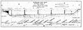
elevation showing "Supposed" soil conditions.
Plan " A "
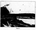
Photo 1
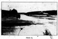
Photo 1a
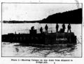
Photo 2
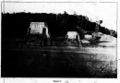
Photo 7
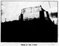
Photo 8
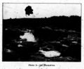
Photo 9
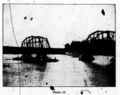
Photo 10
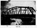
Photo 10a
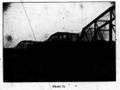
Photo 11


References